
Understanding Converter Fluid Flows
In our article Understanding Torque Converters, we looked at the parts that make up the torque converter and had a brief introduction on the workings of each component. We will focus this article of the fluid flow within the torque converter itself.
When the impeller is driven by the engine crankshaft, the fluid in the impeller rotates in the same direction. When the impeller speed increases, centrifugal force causes the fluid to flow outward from the centre of the impeller and flows along the vane surfaces of the impeller. As the impeller speed rises further, the fluid is forced out away from the impeller toward the turbine. The fluid strikes the vanes of the turbine causing the turbine to begin rotating in the same direction as the impeller.
As the fluid dissipates its energy against the vanes of the turbine, it flows inwards along the vanes of the turbine. When it reaches the interior of the turbine, the turbine’s curved inner surface directs the fluid at the vanes of the stator, and the cycle begins again.
It is important to note that this flow, can be quicker and more powerful at times, and there are also occasions when this flow is almost nonexistent.
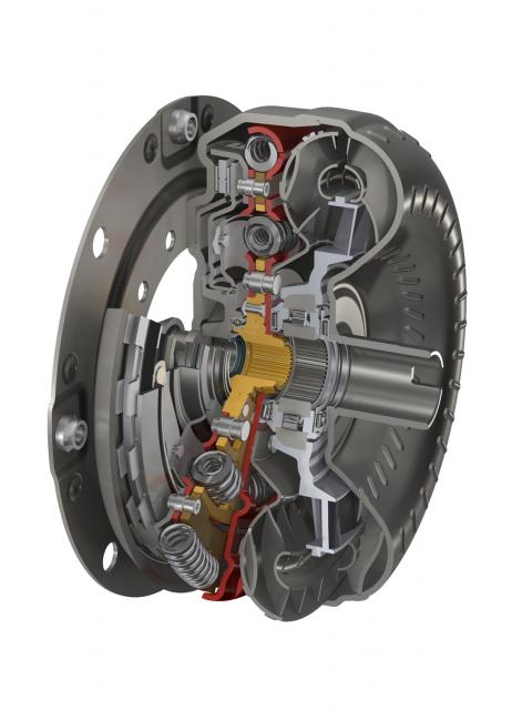
There are two types of fluid flow inside the torque converter. The first is the vortex flow, and the second being the rotary flow. In the below picture, the vortex flow is a spiraling flow which continues as long as there is a difference in speed between the impeller and the turbine. The rotary flow is the fluid flow which circulates with the converter body rotation.
The fluid flow is stronger when the difference in speed between the impeller and turbine is great, eg when the vehicle is accelerating. This is called high vortex. During this time, the flow of fluid leaving the turbine strikes the front of the vanes of the stator and locks it on the stator reaction shaft, preventing it from rotating in the counterclockwise direction. The fluid passing through the stator is redirected by the shape of the vanes and strikes the back of the vanes of the impeller, resulting in an increase in torque over that which is provided by the engine. Without the stator, the returning fluid would interfere with the normal impeller rotation, reducing it severly.
During times of low vortex flow, the fluid coming from the turbine strikes the convex back of the vane rather than the concave face of the vane. This causes the one way clutch to release and the stator freewheels on the reaction shaft. At this point, there is little need for torque multiplication.
As the rotating speed of the impeller and the turbine become closer, the vortex flow decreases and the fluid begins to circulate with the impeller and turbine. This flow is referred to as the rotary flow. This flow is great when the difference in speed between the impeller and turbine is small, as when the vehicle is being driven at a constant speed. This is called the coupling point of the torque converter. At the coupling point, like the low vortex, the stator must freewheel in the clockwise direction. Should the stator fail to freewheel, it would impede the flow of fluid and tend to slow the vehicle.
sources-
http://www.procarcare.com/icarumba/resourcecenter/encyclopedia
http://www.catalogs.com/info/automotive/automatic-transmission.html
http://www.autoshop101.com
To read more about Automatic Transmissions and understanding their components, please view the following links:
Understanding Automatic Transmissions
Understanding Holding Devices for Planetary Gears
Understanding Torque Converters
Understanding Converter Fluid Flows
Understanding the Lock Up Clutch
Understanding the Valve Body 1/2
Understanding the Valve Body 2/2