Understanding Planetary Gears
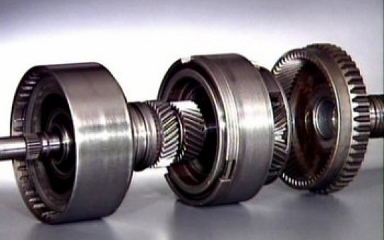
A planetary gear set is a series of three interconnecting gears consisting of a sun gear, several pinion gears and a ring gear. Each pinion gear is mounted to a carrier assembly by a pinion shaft. The sun gear is located in the centre of the assembly; several pinion gears rotate around the sun gear; a ring gear surrounds the pinion gears. This gear assembly is called the “planetary” gears because the pinion gears resemble planets revolving around the sun.
In a planetary gear design, we are able to get different gear ratios forward and reverse, even though the gears are located on the same axis.
Gear ratios
Gear ratios can also be determined in a planetary gear set although it is not something that can easily be changed. The gear ratio of the planetary gear set is determined by the number of teeth of the carrier, ring gear, and sun gear. Since the carrier assembly has no teeth and the pinion gears always operate as idle gears, their number of teeth is not related to the gear ratio of the planetary gear set. However, an arbitrary number needs to be assigned to the carrier in order to calculate the ratio. Simply count the number of teeth on the sun gear and the ring gear. Add these two numbers together and you have the carrier gear number for calculation purposes.
The number of carrier teeth (Cc) can be obtained by the following equation:
Cc = Cr + Cs
Where
Cc = Number of carrier teeth
Cr = Number of ring gear teeth
Cs = Number of sun gear teeth
We will assume Cr is 56 and Cs is 24. When the sun gear is fixed and the ring gear operates as the input member, the gear ratio of the planetary gear set is calculated as:
Ratio = Number output gear teeth / Number of input gear teeth
= Cc / Cr
= 56 + 24 / 56
= 1.429
Therefore, the input member would have to turn almost one and a half times to one turn of the output member.
Operation
The chart below shows the planetary gear operation. Different speeds and rotational directions can be obtained by holding one of the planetary members in a fixed position providing input torque to another member, with the third member used as an output member.
When any two members are held together and another member provides the input turning force, the entire assembly turns at the same time as the input member. Now, the gear ratios from a single planetary set do not give us the desired ratios which take advantage of the optimum torque of the engine. So it is necessary to use two single planetary gear sets which share a common sun gear. This design is basic to most automatic transmissions in production today.
http://www.autoshop101.com
To read more about Automatic Transmissions and understanding their components, please view the following links:
Understanding Automatic Transmissions
Understanding Holding Devices for Planetary Gears
Understanding Torque Converters
Understanding Converter Fluid Flows
Understanding the Lock Up Clutch
Understanding the Valve Body 1/2
Understanding the Valve Body 2/2


