
Understanding the Lock Up Clutch
When the impeller and the turbine are rotating at nearly the same speed, no torque multiplication is taking place. The torque converter is transmitting the input torque from the engine to the transmission at a ratio of almost 1:1. There is however, approximately 4-5% difference in rotational speed between the turbine and the impeller. The torque converter is not transmitting 100% of the power generated by the engine to the transmission, so there is energy loss.
To prevent this, and to reduce fuel consumption, the lock up clutch mechanically connects the impeller and turbine when the vehicle is around 37mph or higher. When the lock up clutch is engaged, 100% of the power is transferred through the torque converter.
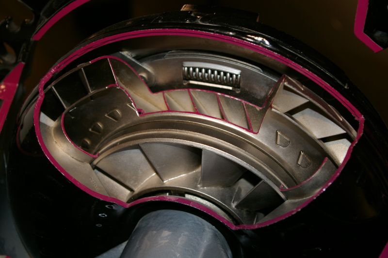
The lock up clutch is installed on the turbine hub, in front of the turbine. The dampening spring absorbs the torsional force upon clutch engagement to prevent shock transfer. The friction material bonded to the lock up piston is the same as that used on the multiplate clutch discs in the transmission.
Operation
When the lock up clutch is actuated, it rotates together with the impeller and turbine. Engaging and disengaging of the lock up clutch is determined by the point at which the fluid enters the torque converter. Fluid can either the converter in the front of the lock up clutch or in the main body of the converter behind the lock up clutch. The difference in pressure on either side of the lock up clutch determines engagement or disengagement.
The fluid used to control the torque converter lock up is also used to remove heat from the converter and transfer it to the engine cooling system through the heat exchanger in the radiator.
Control of the hydraulic fluid to the converter is accomplished by the relay valve and signal valve. Both valves are spring loaded to a position which leaves the clutch in a disengaged position. In the above photo, converter pressure flows through the relay valve to the front lock up clutch. Notice that the main body of the converter hydraulic circuit is connected to the transmission cooler through the bottom land of the relay valve.
The signal valve controls line pressure to the base of the relay valve. When governor pressure or line pressure is applied to the base of the signal valve, line pressure passes through the signal valve and is applied to the base of the relay valve. The relay valve moves up against spring tension diverting converter pressure to the main body of the converter.
When the vehicle is running at low speeds, the pressurized fluid flows into the front of the lock up clutch. The pressure on the front and rear sides of the lock up clutch remains equal, so the lock up clutch is disengaged.
When the vehicle is running at medium to high speeds, the pressurized fluid flows into the area to the rear of the lock up clutch. The relay valve position opens a drain to the area in the front of the lock up clutch, creating an area of low pressure. Therefore, the lock up piston is forced against the converter case by the difference in hydraulic pressure on each side of the lock up clutch. As a result, the lock up clutch and the converter case rotate together.
sources-
http://www.procarcare.com/icarumba/resourcecenter/encyclopedia
http://www.catalogs.com/info/automotive/automatic-transmission.html
http://www.autoshop101.com
To read more about Automatic Transmissions and understanding their components, please view the following links:
Understanding Automatic Transmissions
Understanding Holding Devices for Planetary Gears
Understanding Torque Converters
Understanding Converter Fluid Flows
Understanding the Lock Up Clutch
Understanding the Valve Body 1/2
Understanding the Valve Body 2/2