
Understanding Torque Converters
The torque converter plays a number of roles for a motor vehicle:
- Multiplies torque generated by the engine
- Serves as an automatic clutch which transmits engine torque to the transmission
- Absorbs torsional vibration of the engine and drivetrain
- Smoothes out engine rotation
- Drives the oil pump of the hydraulic control system
In simple terms, the torque converter provides a means of power from the engine to the input shaft of the transmission. It acts like an automatic clutch to engage engine torque to the transmission and also allows the engine to idle while the vehicle is standing still with the transmission in gear.
The torque converter can either multiply the torque generated by the engine or function as a fluid coupling. It also serves as the engine flywheel to smooth out engine rotation as its inertia helps to maintain crankshaft rotation between piston power pulses. It tends to absorb torsion vibration from the engine and drivetrain through the fluid medium since there is no direct mechanical connection through the converter.
In addition, the rear hub of the torque converter body drives the transmission oil pump, providing a volume of fluid to the hydraulic system. The pump turns any time the engine rotates, which is an important consideration when a vehicle is towed. If the vehicle is towed with the drive wheels on the ground and the engine is not running, the axles drive the transmission output shaft and intermediate shaft on bearings that receive no lubrication. There is a great potential for damage if the vehicle is towed for a long distance or at greater than low speeds.
The torque converter is mounted on the input side of the transmission gear train and connected to a drive plate. The drive plate, or flex plate is used to connect the converter to the crankshaft flywheel flange of the engine. The ring gear, which the starter motor engages to turn the engine, is attached to the drive plate.
Torque Converter Components
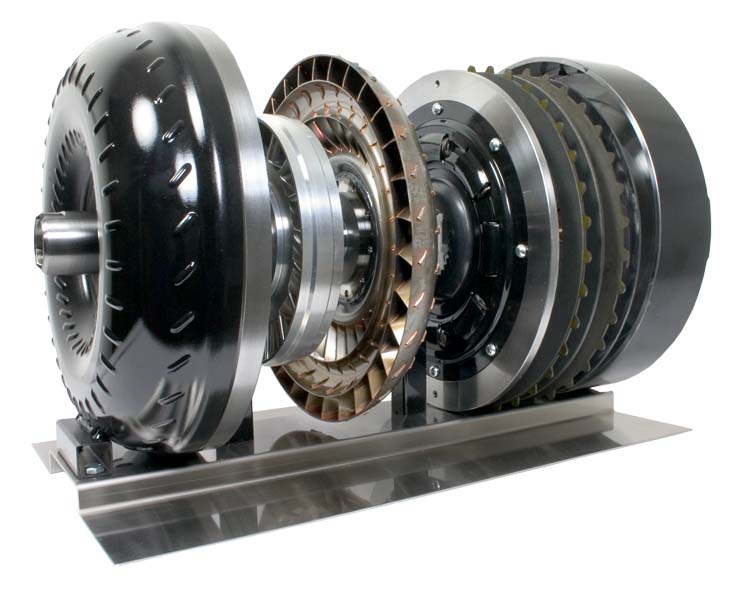
The torque converter has three major components: the Pump Impeller (or Impeller), the Turbine Runner (or Turbine) and the Stator.
Pump Impeller – is integrated with the torque converter case, with many curved vanes that are radially mounted inside. A guide ring is installed on the inner edges of the vanes to provide a path for smooth fluid flow. When the impeller is driven by the engine crankshaft, the fluid in the impeller rotates with it. When the impeller speed increases, centrifugal forces cause the fluid to flow outward, toward the turbine.
Turbine Runner – is located inside the converter case but is not connected to it. The input shaft of the transmission is attached by splines to the turbine hub when the converter is mounted to the transmission. Many cupped vanes are attached to the turbine. The curvature of the vanes is opposite from that of the impeller vanes. Therefore, when the fluid is thrust from the impeller, it is caught in the cupped vanes of the turbine and torque is transferred to the transmission input shaft, turning it in the same direction as the engine crankshaft.
Before moving onto the next component of the torque converter, we need to examine the fluid cupling whose components we have just described. When first automatic transmissions were introduced in the 30’s – 40’s, the only components were the impeller and turbine. This provided a means of transferring torque from the engine to the transmission and also allowed the vehicle to be stopped in gear while the engine idles. However, these early fluid couplings had the problem of poor acceleration. The engine would labour until the vehicle picked up speed. The problem occurred because the vanes on the impeller and turbine are curved in the opposite direction to one another. Fluid coming off of the turbine is thrust against the impeller in a direction opposite to engine rotation.
Notice the illustration of the stator below. The arrow drawn with the dashed lines represents the path of the fluid if the stator was not there, such as in a fluid coupling. Not only is engine horsepower consumed to pump the fluid initially, but now it also has to overcome the force of the fluid coming from the turbine. The stator was introduced to the design to overcome the counterproductive force of fluid coming from the turbine opposing engine rotation. It not only overcomes the problem, but also has the added benefit of increasing torque to the impeller.
Stator – is located between the impeller and the turbine. It is mounted on the stator reaction shaft which is fixed to the transmission case. The vanes of the stator catch the fluid as it leaves the turbine runner and redirects it so that it strikes the back of the vanes of the impeller, giving the impeller an added boost of torque. The benefit of this added torque can be as much as 30-50%.
The one way clutch allows the stator to rotate in the same direction as the engine crankshaft. However, if the stator attempts to rotate in the opposite direction, the one way clutch locks the stator to prevent it from rotating. Therefore, the stator is rotated or locked depending on the direction from which the fluid strikes against the vanes.
sources-
http://www.procarcare.com/icarumba/resourcecenter/encyclopedia
http://www.catalogs.com/info/automotive/automatic-transmission.html
http://www.autoshop101.com
To read more about Automatic Transmissions and understanding their components, please view the following links:
Understanding Automatic Transmissions
Understanding Holding Devices for Planetary Gears
Understanding Torque Converters
Understanding Converter Fluid Flows
Understanding the Lock Up Clutch
Understanding the Valve Body 1/2
Understanding the Valve Body 2/2